

As a manufacturer, IWM craftsmen weave our wire mesh to meet our customers’ exacting specifications ensuring consistent product quality. IWM is in continuous production of plain weave wire mesh constructed of aluminum, low carbon steel, and stainless steel wire. More details concerning material specifications can be found in our materials technical guide. Below, please find specifications concerning terminology, industry standards, and construction guidelines for your design considerations.
Terminology
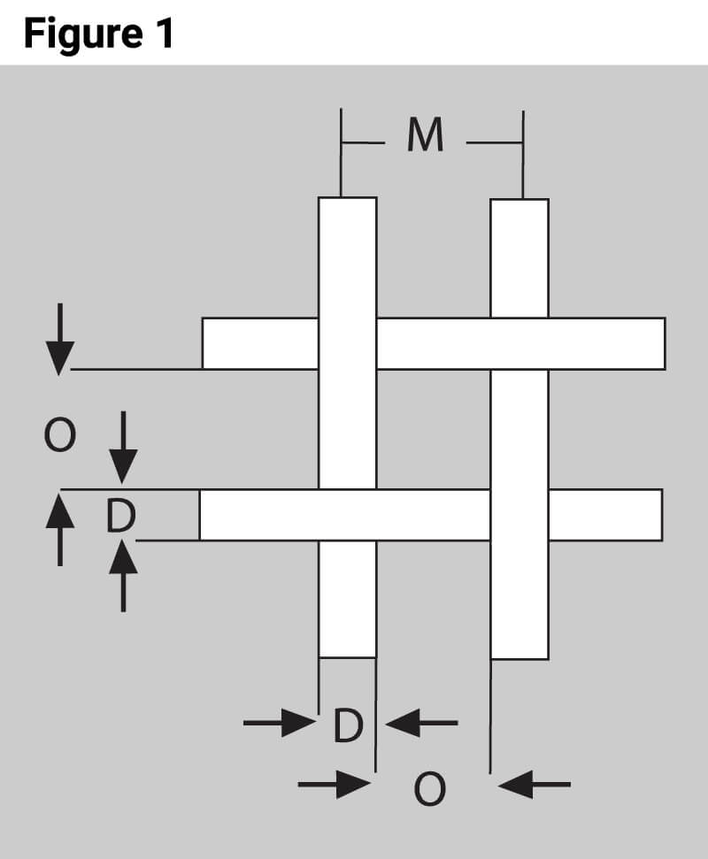
Mesh Count is the number of openings or apertures (Figure 1. O) which can be counted per every linear inch of wire mesh. This is typically designated for both directions of the mesh. Therefore, a wire mesh which has ten openings per inch as measured across both its width and length would be designated a 10 x 10 mesh or Number 10 mesh.
Pitch (Figure 1. M) is the sum of the aperture or opening size (Figure 1. O) and the wire’s diameter or gauge size (Figure 1. D). Details concerning wire gauges and the wire sizes IWM offers can be found in the Technical section concerning Wire Sizes.
The Warp Wire in wire mesh is the wire running parallel to direction of the wire mesh length or its roll length. The Weft or Fill Wire runs parallel to the width of the wire mesh or the roll’s width.
Weave Types
There are several different general weave types of wire mesh. Twill Weaves refer to woven mesh which has two or more warp wires passing over and under two or more weft wires. This weaving method is typically used for wire mesh used for filtration media.
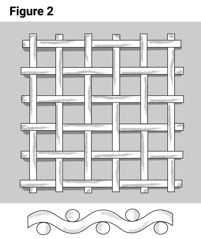
By far the most common type of mesh weave is a Plain Weave or plain crimp wire mesh, which is the weave type IWM predominately offers. A plain weave mesh is where the warp wires and weft wires weave over and under each individual wire strand in each direction. This is depicted in Figure 2.
Additionally, IWM offers a Lockstitch Weave. Similar to a plain weave, the weft wires and warp wires are woven over and under one another. However, a lockstitch is achieved when placing two warp wires closer together when setting up the comb or reed, which separates the warp wires. These lockstitches can be positioned along the width of the mesh roll to prevent the fraying of edges when trimming or slitting the mesh to narrower widths.
Lockstitch Weave
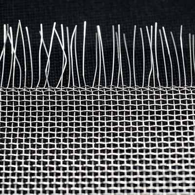
Extended Raw Edge
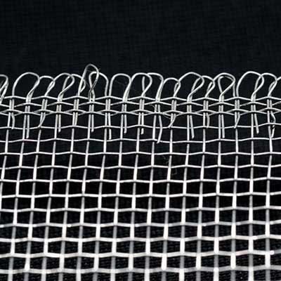
Tucked Edge
Edge Finish
An edge finish is typically designated for a wire mesh if it’s not a raw edge. A Raw Edge represents a mesh with exposed weft wires. Finished edges can be achieved by tucking or looping the weft wires to achieve a finished edge. A Tucked Edge refers to the exposed weft wire being tucked back around the edge warp wires so that the end of the weft wire is no longer exposed. A Selvage Edge or looped edge provides a finished edge for the wire mesh by continuously weaving the weft wire so that there is no exposed wire ends along the length of the roll of mesh. IWM offers both finished and unfinished edges for its wire mesh.
Space Cloth in the context of wire mesh represents mesh which is specified by its opening size rather than its mesh count. Wire mesh may be designated by its percent of open area which can be calculated as follows when its mesh count and wire diameters are the same across its width and length.

Market Grade or standard grade represents a family of wire meshes. These wire meshes represent a specific mesh count with a correlating single wire diameter. A list of market grade meshes which are offered by IWM can be found in the following table for low carbon steel mesh.
| Mesh | Wire Diameter (inch) |
Opening (inch) |
% Open Area |
|---|---|---|---|
| 4 x 4 | 0.018 | 0.232 | 86 |
| 5 x 5 | 0.018 | 0.182 | 83 |
| 6 x 6 | 0.016 | 0.151 | 82 |
| 8 x 8 | 0.011 | 0.114 | 83 |
| 10 x 10 | 0.010 | 0.090 | 81 |
| 12 x 12 | 0.009 | 0.074 | 80 |
| 14 x 14 | 0.008 | 0.063 | 79 |
| 16 x 16 | 0.007 | 0.056 | 79 |
| Mesh | Wire Diameter (inch) |
Opening (inch) |
% Open Area |
|---|---|---|---|
| 18 x 18 | 0.006 | 0.050 | 80 |
| 20 x 20 | 0.005 | 0.045 | 81 |
| 24 x 24 | 0.005 | 0.037 | 77 |
| 30 x 30 | 0.005 | 0.028 | 72 |
| 35 x 35 | 0.005 | 0.024 | 68 |
| 40 x 40 | 0.005 | 0.020 | 64 |
| 50 x 50 | 0.005 | 0.015 | 56 |
| 60 x 60 | 0.005 | 0.012 | 49 |
Industry Standards
Both ASTM E 2016 and ISO 9044 are current industry standards concerning woven wire mesh for general, particle separation, and screening applications. Each specification covers terminology, standard tolerances, and inspection criteria & methodology.
For fenestration products, the Screen Manufacturing Association maintains SMA 1201 for specifications concerning wire screens used for the prevention of insect ingress for windows and doors and SMA 6001 concerning metal protection screens. Although currently withdrawn, ANSI/IWS 089:1990 is still referenced on legacy insect screen specifications previously developed by the Insect Screening Weavers Association.
Construction Guidelines & Design Considerations
Material selection is typically at the forefront of your consideration when designing your woven wire mesh configuration. IWM offers wire mesh in aluminum, low carbon steel, stainless steel, and copper alloys. Details concerning material specifications can be found in our materials technical guide with information to include physical properties such as density, tensile strengths, electrical and thermal conductivity.
Electromagnetic Considerations
Metal wire mesh is a useful material when designing reflective surfaces when weight is a consideration. Satellite dishes and antenna panels may be constructed with woven wire mesh as the reflective surface for certain electromagnetic frequencies. The panel can be constructed of mesh or imbedded in the panel’s construction. The mesh size or aperture only needs to be sized to ensure the wavelength of the signal is reflected. When the transmission frequency is defined, wavelength can be calculated as follows.

For transmit and/or receive, a general rule is to achieve a surface accuracy of one-tenth the transmitted frequency’s wavelength. Thus, for a C-Band VSAT frequency of 4/6 GHz having a wavelength of 50mm (300/6), the surface tolerance would be 5mm, which can be met using several market grade woven wire mesh sizes.
Additionally, wire mesh can be used to shield or attenuate electromagnetic signals. When designing for electromagnetic compatibility (EMC), the wire mesh construction (wire diameter, mesh count, % opening) will determine the shield effectiveness (SE) expressed in decibels (dB). NASA Contractor Report 4784 (Pg. 35-36) is a useful design guide when considering mesh construction for EMI shielding.
Conductivity & Grounding Considerations
Another facet when designing for electromagnetic compatibility is consideration for grounding. Metal wire mesh is used as an electrical grounding member within electrical assemblies and composite structures. For applications where high conductivity is required, IWM’s copper and aluminum (5154A) materials are typically desired. For electrically dissipative applications, IWM’s commercial bronze (C220), carbon steel (1005), or stainless steel (304) may be appropriate.
For high voltage dissipative protection, such as for Lighting Strike Protection (LSP), IWM’s aluminum (5154A) mesh can be used as a conductive member within the composite layup or composite prepreg components used in the manufacture of windmills, towers, and aerostructures.
Size & Dimensional Considerations
Depending on end use, wire mesh can be acquired as roll goods or discrete fabricated to size parts.
For Roll Goods, IWM offers custom ordered woven roll widths, as well as standard woven widths of 24in., 36in, 48in., 60in, and 72in. Standard roll lengths start at 100ft with capability to 3000ft dependent on material type. Standard finished roll goods width and overall length tolerances would be -0.00/+0.25in. unless otherwise requested.
Overall width and edge finish should be considered for end use. IWM offers trimmed edge(s) as well as slit to width sizes starting at 1inch. Further details concerning IWM slitting and cut to size capabilities can be found at the Contract Manufacturing section under Products & Capabilities.
Woven wire mesh thickness is dependent on its wire diameter. Unless otherwise specified, IWM meets ASTM E 2016 standards concerning tolerances for wire diameters. The below table lists standard wire diameter tolerances for IWM standard woven wire mesh for aluminum, copper alloys, stainless, and low carbon steel.
| Material Type | Wire Diameter Range | Tolerance |
|---|---|---|
| Stainless Steel | < 0.0049 in. | +/- 0.0001 in.
+/- 0.003 mm. |
| Aluminum, Low Carbon Steel,
Stainless Steel |
0.005 – 0.008in. | +/- 0.0002 in.
+/- 0.005 mm. |
| Aluminum, Low Carbon Steel,
Stainless Steel, & Copper Alloys |
0.009 – 0.012in. | +/- 0.0003 in.
+/- 0.008 mm. |
| Aluminum, Low Carbon Steel,
Stainless Steel, & Copper Alloys |
0.013 – 0.020in. | +/- 0.0004in.
+/- 0.010mm. |
| Aluminum, Stainless Steel | 0.021 – 0.025in. | +/- 0.0004in.
+/-0.010mm. |
| Stainless Steel | 0.026 – 0.033in. | +/- 0.0005in.
+/- 0.013mm. |
| Stainless Steel | 0.033 – 0.063in. | +/- 0.0008in.
+/- 0.020mm. |
The overall thickness of a woven wire mesh will not be less than the bottom tolerance range of its combined thickness of its warp and shute wire diameters. To achieve a smoother or compressed mesh thickness, IWM can provide Calendaring Services. A calendared mesh can be advantageous for post processes such as forming, stamping, or when using as media within composite structure or molded parts. For additional information on calendaring and other post processes, please visit our Contract Manufacturing section under Products & Services.
Selection of Treatments & Finishes
The metal treatments and finishes of your mesh products will affect the mesh’s physical attributes such as ductility, its electrical conductivity or resistance, its resistance to corrosion or chemicals, its abrasion resistance, its reflectiveness, or its resistance to color fade throughout the product’s life cycle. IWM application engineering can support such design considerations concerning your finishes. We welcome you to contact us at solutions@iwmesh.com for more guidance concerning your product finishes and design.
For ease of reference, please see the table below for available mesh treatments and finishes for the different mesh materials offered by IWM. For additional details concerning treatments and finishes offered at IWM please visit our Contract Manufacturing section under Products & Services.
| Mesh Material Type | Metal Treatments & Finishes | |||||
|---|---|---|---|---|---|---|
| Copper Flashed |
Galvanized | Cleaned Only |
Varnished | Painted | Powder Coated |
|
| Aluminum | ✔ | ✔ | ✔ | ✔ | ||
| Copper/Bronze | ✔ | ✔ | ||||
| Low Carbon Steel | ✔ | ✔ | ✔ | ✔ | ||
| Stainless | ✔ | ✔ | ✔ |
| Mesh Material Type | ||||
|---|---|---|---|---|
| Metal Treatment & Finishes |
Aluminum | Copper/ Bronze |
Low Carbon Steel |
Stainless |
| Copper Flashed | ✔ | |||
| Galvanized | ✔ | |||
| Passivated | ✔ | |||
| Cleaned Only | ✔ | ✔ | ||
| Varnished | ✔ | ✔ | ||
| Painted | ✔ | ✔ | ✔ | |
| Powder Coated | ✔ | ✔ | ✔ |